Misty Backpack for Arduino
The Misty Backpack for Arduino is a microcontroller embedded in a magnetic mount that communicates with your skills via the UART serial port on Misty's back. You can use the Arduino-compatible backpack with sensors and other hardware to extend the capabilities of Misty's native hardware.
Schematics
Note: The backpack cover that arrives with Misty II does not include a development board. The Misty Backpack for Arduino must be purchased separately.
What's in the Box?
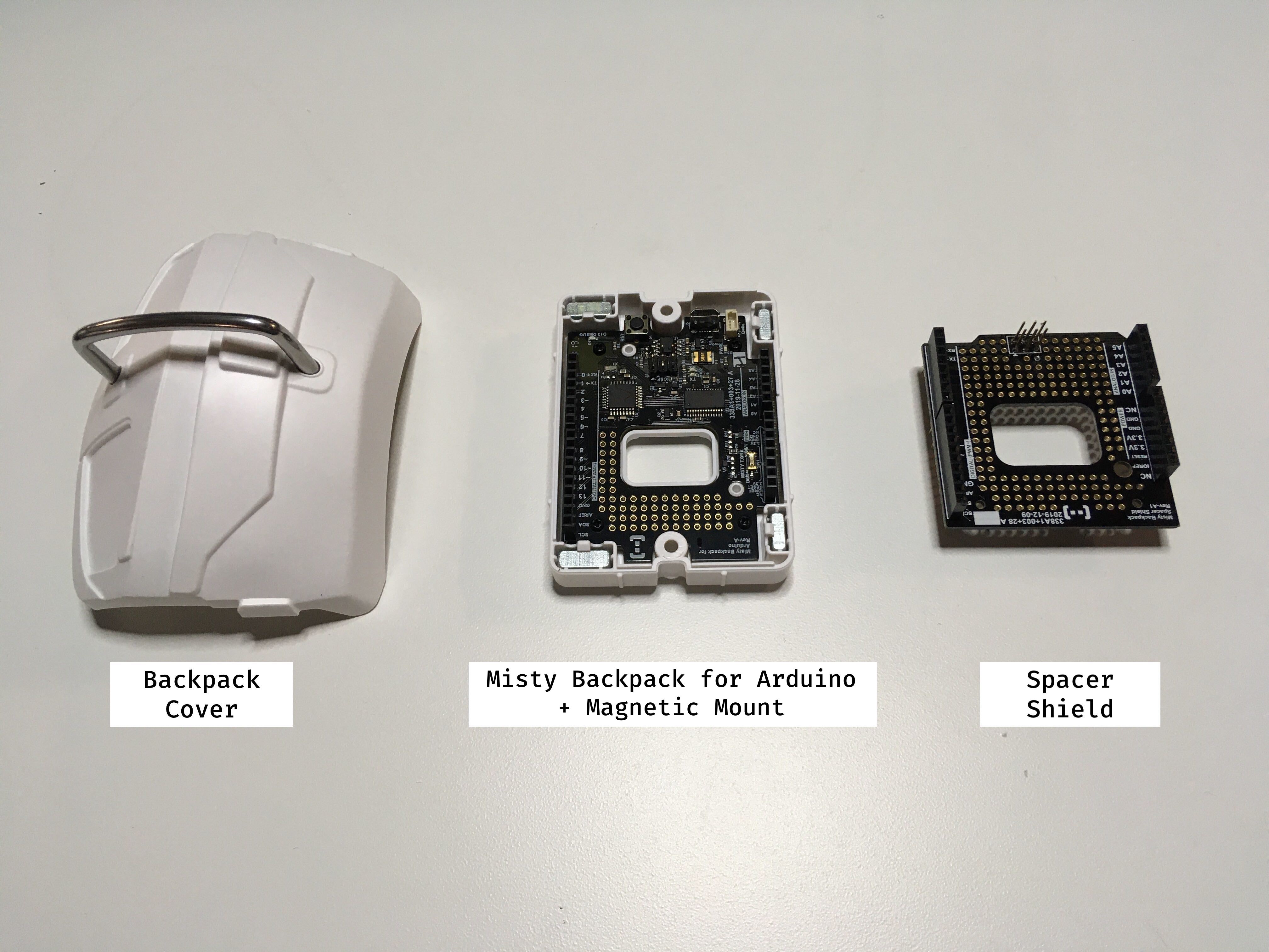
The box for your Misty Backpack for Arduino includes:
- Backpack Cover
- Misty Backpack for Arduino & Magnetic Mount
- Spacer Shield
Important Note: If you are having trouble sending messages to Misty from your backpack, check the position of the Misty TX/RX switch. Most boards arrive with the switch at D0/1 (hardware serial), but some boards may arrive with the switch at D8/9 (software serial). See the images in the Misty TX/RX section below for more information.
Specifications
The Misty Backpack for Arduino:
- uses a 3.3v logic board (not 5v)
- uses a baud rate of 9600/8-N-1 for serial data transmission
- includes a Sparkfun QWIIC connector wired to the SCL and SDA pins on the microcontroller
- has a USB micro port for programming
- includes built-in pins configured to interface with Misty's UART serial port
- is embedded in a mount with magnets attaching the microcontroller to Misty
- provides the ability to switch the default serial TX and RX pins from pins 0 and 1 (default) to pins 8 and 9
QWIIC Connector
The QWIIC system makes it easy to connect SparkFun sensors and other kinds of hardware to Misty's Arduino-compatible backpack. Misty's backpack comes with a built-in QWIIC Connector that operates through the SDA and SCL pins on the board. This connector uses the Inter-integrated Circuit (I2C) communication protocol and can connect directly to any SparkFun QWIIC Sensors or Accessory Boards.
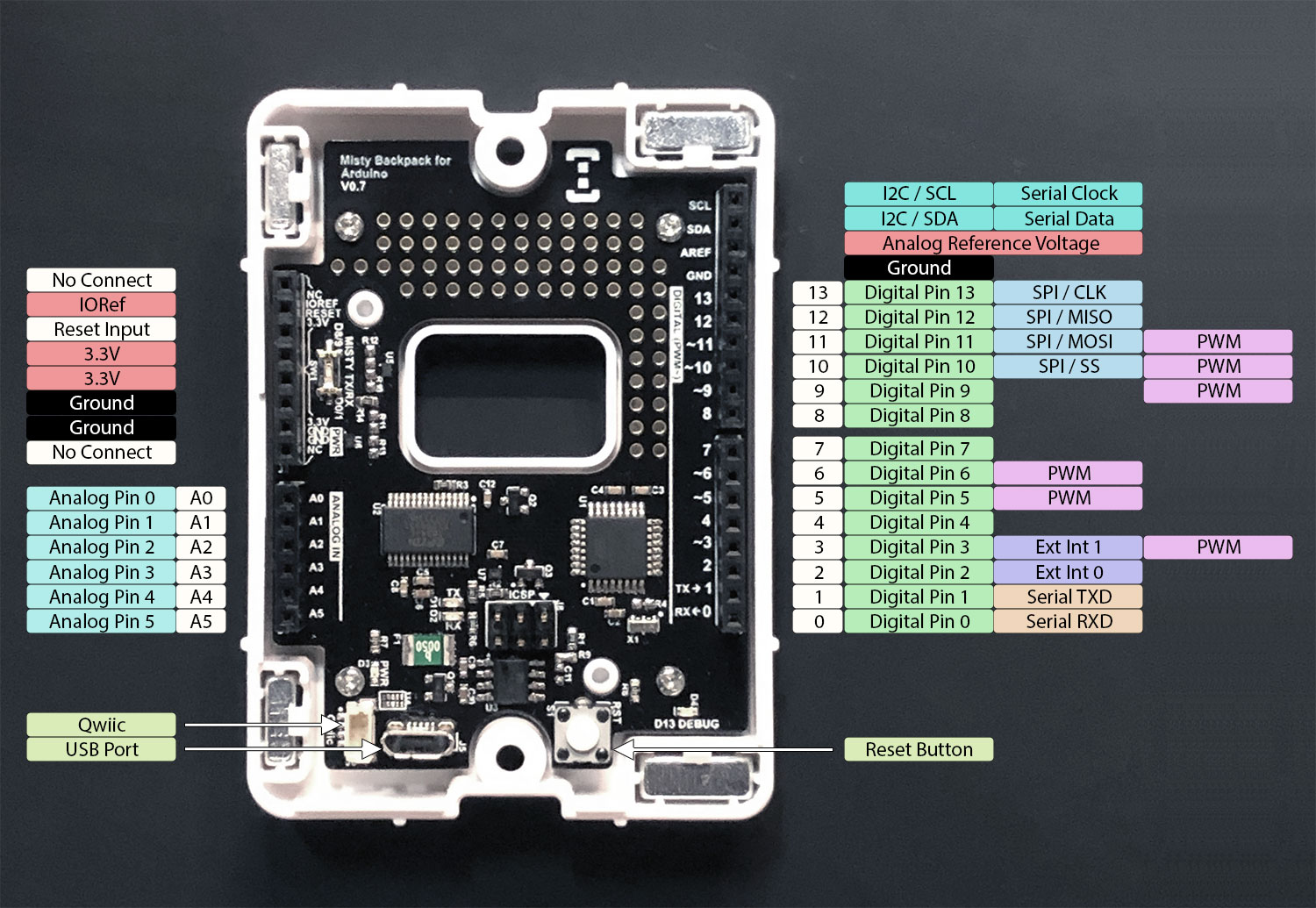
Input & Output
You can use the digital pins on the Misty Backpack for Arduino for either input or output. These pins operate at 3.3v logic. With the exception of the difference in voltage, the pinout for this board is the same as the pinout for the Arduino Uno. For more information about the function of each pin, see the Input and Output section of the documentation for the Arduino Uno.
Shield Compatibility
The Misty backpack has Arduino-compatible headers. It has a similar pinout to the Arduino Uno, and is compatible with most 3.3v-compatible Uno Shields.
Important: Arduino Uno shields that require 5v must pull power from Misty's USB port or another external power source, and require a logic level converter between any input/output (I/O) lines shared with Misty's backpack. Be sure to understand the specific power requirements of any shields before using them with Misty's backpack.
Using the Spacer Shield
You can connect the spacer shield to Misty's Arduino-compatible backpack to create extra space between the backpack and any connected shields. This helps prevent larger shields from interfering with Misty's chassis.
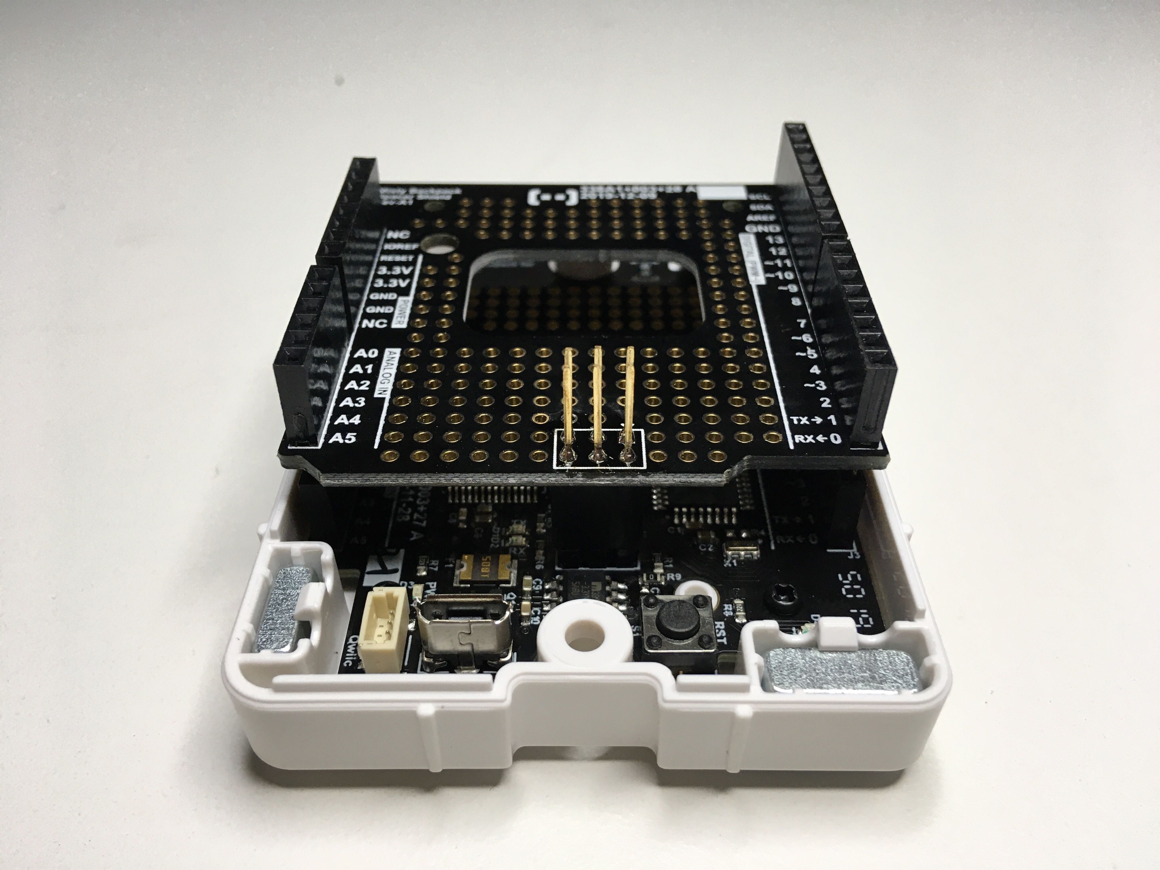 A spacer shield connected to the Misty Backpack for Arduino.
Programming the Misty Backpack for Arduino
The Misty Backpack for Arduino uses an ATmega328P microcontroller pre-programmed with a bootloader that allows you to upload code directly from the Arduino IDE. When you upload your code, you must target the Arduino Pro or Pro Mini board and the ATmega328P (3.3v, 8MHz) processor.
Follow these steps to configure the Arduino IDE to upload code to Misty's Arduino-compatible backpack:
- Download and install the Arduino IDE.
- Connect the Misty backpack to your computer via the backpack's USB micro port.
- Open the IDE and select Tools from the top menu.
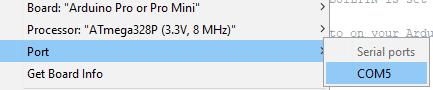
- From the Board sub-menu, select Arduino Pro or Pro Mini.
- From the Processor sub-menu, select ATmega328P (3.3V, 8MHz).
- From the Port sub-menu, select the port that the microcontroller is connected to. (Your port number may be different than what is pictured here).
Tip: For more information about writing sketches for Arduino microcontrollers, see the reference materials and tutorials hosted on the Arduino website.
Note: When using hardware serial to communicate with Misty (pins D0 and D1), you must remove the board from Misty before you can upload a new sketch. If you are using the software serial pins (D8 and D9), you can upload a new sketch without disconnecting the board.
Serial APIs
When you write code for Misty's Arduino-compatible backpack (or any other Arduino microcontroller), you can use the Serial library to configure communication between the external development board and your robot.
Tip: For runnable examples of .ino sketches and JavaScript skill code for serial communication, see the serialReadWrite sample code on GitHub.
In the setup() function for your sketch, use the Serial.begin() function to set the data transfer rate to 9600 baud. Then, in the loop() function, use Serial.println() to send data to Misty. For greatest flexibility in handling, we typically recommend formatting this data as a JSON string. Here's an example:
void setup() {
  Serial.begin(9600);
}

void loop() {
    delay(1000);
    Serial.println("{\"message\":\"Hello, Misty! This is your backpack talking.\"}");
}
Note: This example assumes that you are using the default pins for transmitting and receiving data over hardware serial (pins D0 and D1). If you are using the pins for software serial (pins D8 and D9), you must use the SoftwareSerial library to send and receive data from Misty.
To read serial data, you must register for SerialMessage events in your skill code. SerialMessage events occur when Misty receives a message through the receiver (RX) pin of her UART serial port.
The following example demonstrates how to handle serial messages in a JavaScript skill. By default, the data for SerialMessage events is processed by a _SerialMessage() callback function. You define how this callback handles the message in your skill code.
// Return the value of the "SerialMessage" property in the
// SerialMessage data object
misty.AddReturnProperty("SerialMessage", "SerialMessage");

// Register for SerialMessage events. Set the debounce rate to 0, or
// use the rate defined in the sketch. Set `keepAlive` to `true`, so
// the event does not unregister after the first callback triggers.
misty.RegisterEvent("SerialMessage", "SerialMessage", 0, true);

function _SerialMessage(data) {
    try{
        if(data !== undefined && data !== null) {
            var obj = JSON.parse(data.AdditionalResults[0].Message);
            var message = obj.message;
        }
    }
    catch(exception) {
        misty.Debug("Exception" + JSON.stringify(exception));
    }
}
Finally, you can use the WriteSerial command in your skill code to send messages from Misty to an external development board. (The WriteSerial command is available in Misty's HTTP API, and .NET SDK libraries.)
Misty TX/RX Switch
The Misty Backpack for Arduino supports hardware serial communication over pins D0 and D1. These pins are wired by default to interface with the serial port on Misty's back.
In addition to this default, you can use the Misty TX/RX switch on Misty's Arduino-compatible backpack to toggle the receiver and transmitter pins from D0 and D1 (hardware serial) to D8 and D9 (software serial). This is useful when you want to connect a shield that uses serial communication over the default hardware serial pins.
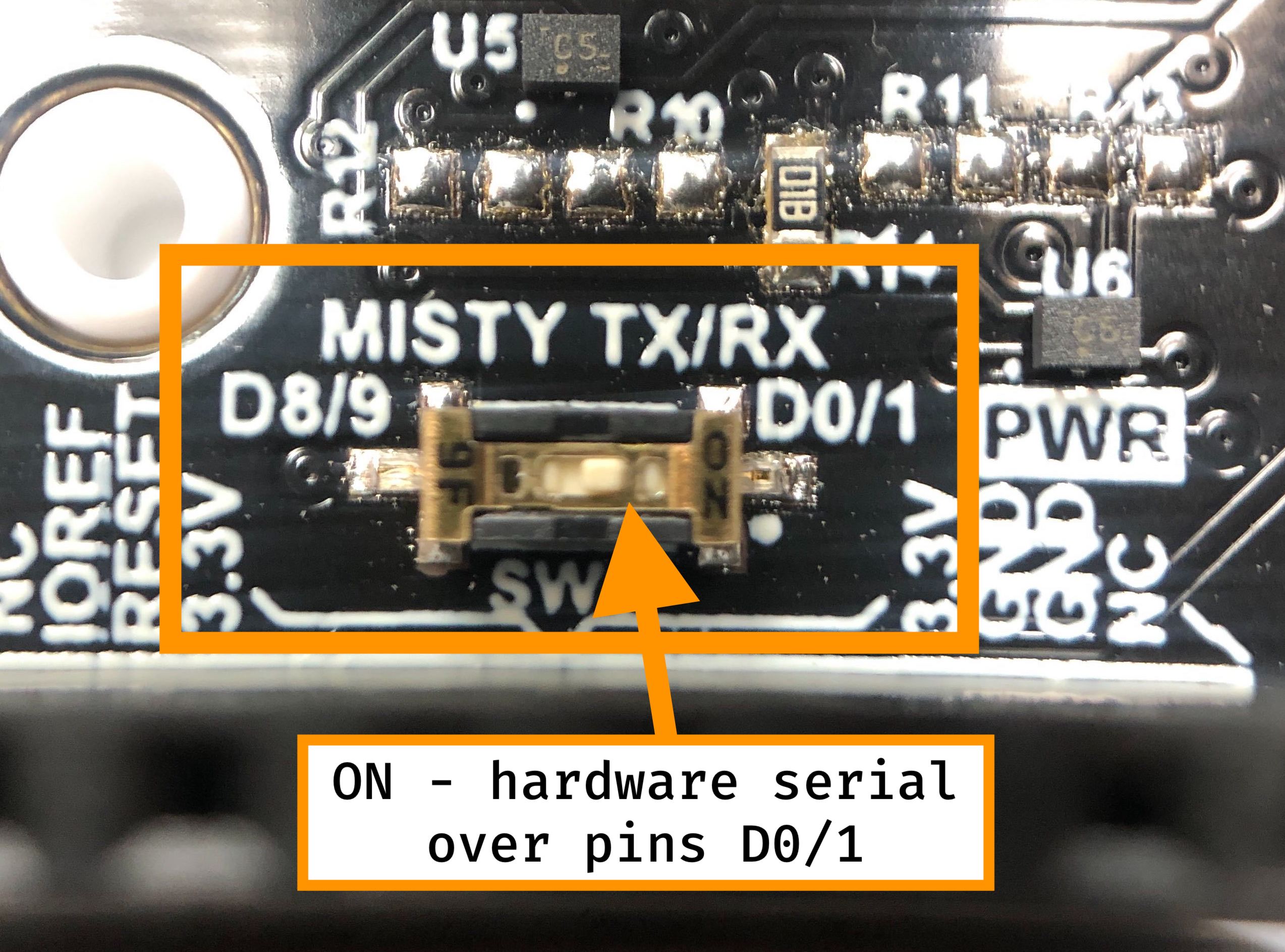
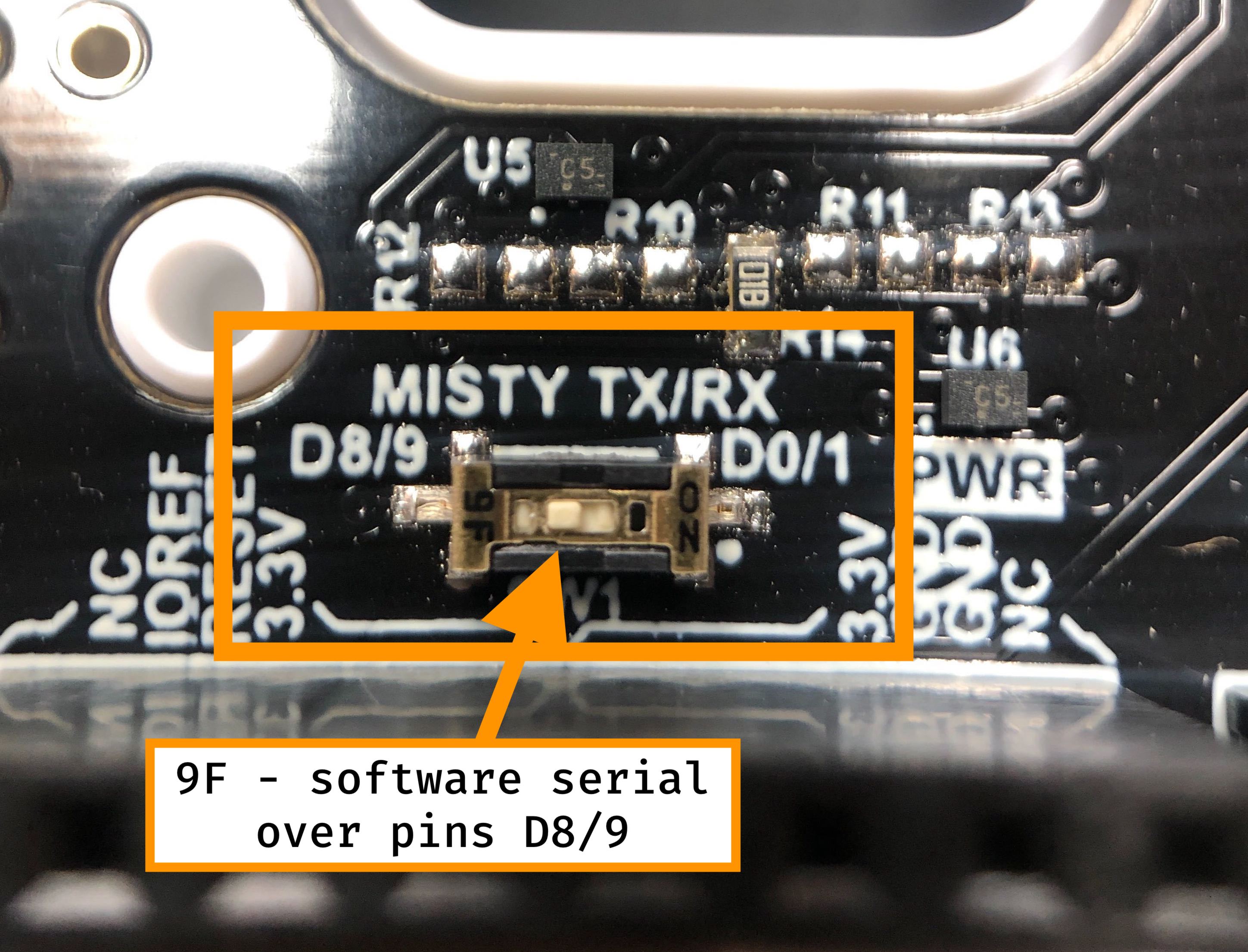
Note: When using pins D8 and D9 for software serial communication, you must use the SoftwareSerial library (instead of the Serial library) to communicate with Misty.